Gestion des masques
Gérer tous les masques et formes dessinées pour l’image actuelle.
Ce module permet de créer, renommer, modifier et supprimer des formes. Vous pouvez modifier les formes d’un masque dessiné, regrouper des formes et les combiner à l’aide d’opérateurs définis.
La ligne supérieure du panneau du module gestion des masques contient des boutons qui peuvent être utilisés pour créer de nouvelles formes. Ce sont les mêmes que dans l’interface Masque dessiné des modules de traitement.
Le panneau sous ces boutons affiche une liste de tous les masques et formes individuelles définis pour l’image actuelle.
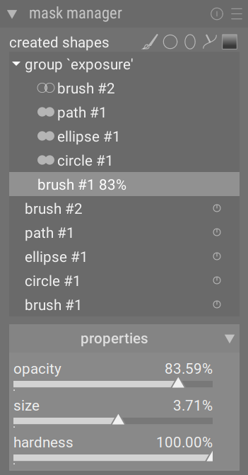
Groups of shapes forming a drawn mask are displayed with a headline in the form “group <module_name>” to indicate the module in which they are used, with the constituent shapes listed below. The list of mask groups is followed by a list of all individual shapes that have been generated in the context of the current image (which also repeats the shapes that are part of a group). If a shape is in use by any drawn masks this is indicated by a symbol to the right of the shape name.
🔗Formes
Par défaut, chaque forme reçoit un nom généré automatiquement, composé du type de forme (Pinceau, Cercle, Ellipse, Chemin, Dégradé) et d’un entier incrémenté automatiquement. Vous pouvez renommer une forme en faisant un double-clic sur son nom actuel. C’est une bonne habitude de donner aux formes et aux groupes des noms significatifs, surtout si vous avez l’intention de réutiliser la même sélection dans différents masques.
Si une forme a une opacité réduite, celle-ci sera affichée à droite du nom de la forme. Une icône représentant le Opérateurs d’ensemble (modes) choisi est affichée à gauche (sauf pour la première forme d’un groupe, qui n’a pas de forme précédente avec laquelle elle peut être combinée).
Cliquez sur le nom d’une forme pour afficher la forme sélectionnée sur le canevas de l’image avec tous ses contrôles, vous permettant de modifier les propriétés de cette forme uniquement. Ceci est particulièrement utile lorsqu’il y a de nombreuses formes qui se chevauchent dans un masque, ce qui rend difficile la sélection de la bonne avec la souris. De même, si vous sélectionnez une forme à l’écran à l’aide d’un contrôle du masque d’un module de traitement, cette forme sera sélectionnée dans le gestionnaire de masques.
Cliquez avec le bouton droit de la souris sur le nom d’une forme pour afficher un menu contenant des options supplémentaires (voir ci-dessous).
Remarque : darktable conserve toutes les formes qui ont déjà été définies pour l’image actuelle, sauf si vous les supprimez explicitement. Si vous choisissez d’inclure l’historique de développement lors de l’exportation d’une image, toutes les formes définies seront exportées avec l’image. Attention, si la liste des formes est très longue, l’espace requis pour stocker ces formes peut dépasser la taille limite de certains formats de fichiers. Cela peut entraîner l’échec de la création d’étiquettes dans le fichiers XMP lors de l’exportation.
🔗Masques & groupes
Les masques dessinés sont construits en ajoutant à l’image un groupe de formes dans l’ordre où elles sont listées (de haut en bas – dans l’ordre d’affichage des modules de traitement). Chaque forme ajuste le masque existant à l’aide de l’un des cinq opérateurs d’ensemble logique (voir ci-dessous). L’ordre étant important, il est également possible de déplacer les formes vers le haut et vers le bas dans la liste à l’aide d’un Clic-droit.
Cliquer sur le nom d’un groupe dans Gestion des masques développe ce groupe en affichant la liste de ses formes constituantes. Les formes correspondantes sont affichées sur l’image centrale. Alternativement, lorsque la Gestion des masques est active, vous pouvez développer ce groupe en montrant les formes du masque dans le module de traitement correspondant.
Faites un Clic-droit sur le nom d’un groupe pour afficher un menu contenant des options permettant d’ajouter des formes nouvelles ou existantes au groupe. Ce menu propose aussi de supprimer les formes non utilisées ou le groupe.
Faites un Clic-droit sur l’une des formes utilisées dans le groupe pour examiner la part que prend cette forme dans la création, par ce groupe, du masque global comme suit :
- Enlever du groupe
- Enlève la forme du masque actuel.
- Inverser la forme
- Inverse la polarité de la forme sélectionnée.
- Mode
- Choisissez comment cette forme va se combiner avec le masque précédent en sélectionnant l’un des cinq opérateurs d’ensemble définis ci-dessous.
- Monter/Descendre
- Monte ou descend la forme dans la liste.
Vous pouvez également créer vos propres groupes avec des formes existantes en sélectionnant celles que vous souhaitez regrouper, en faisant dessus un Clic-droit et en choisissant Regrouper les formes.
🔗Propriétés
Expand the properties section to change the properties (opacity, size, rotation, feather, hardness) of the currently selected shape(s).
Si un groupe est sélectionné, les limites souples des curseurs tentent d’empêcher les distorsions irréversibles. Cela pourrait se produire si certaines formes étaient poussées à leurs valeurs extrêmes tandis que d’autres resteraient ajustées. Dans ce cas, l’inversion du mouvement ne ramènerait pas à la situation d’origine. Cependant, comme toutes les limites souples, elles peuvent être forcées.
Si un stylet (par exemple Wacom) est détecté, des options supplémentaires sont aussi affichées pour contrôler son utilisation par darktable :
- pressure
- Controls how the pressure reading of a graphics tablet impacts newly generated drawn mask brush strokes. You can control the brush width, hardness and opacity. “Absolute” control means that the pressure reading directly defines the attribute with a value between 0% and 100%. “Relative” means that the pressure reading adjusts the attribute between zero and the pre-defined default value (default off).
- smoothing
- Sets the level for smoothing of drawn mask brush strokes. Stronger smoothing leads to fewer nodes and easier editing at the expense of lower accuracy.
🔗Opérateurs d’ensemble (modes)
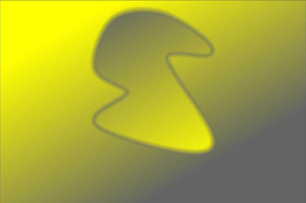
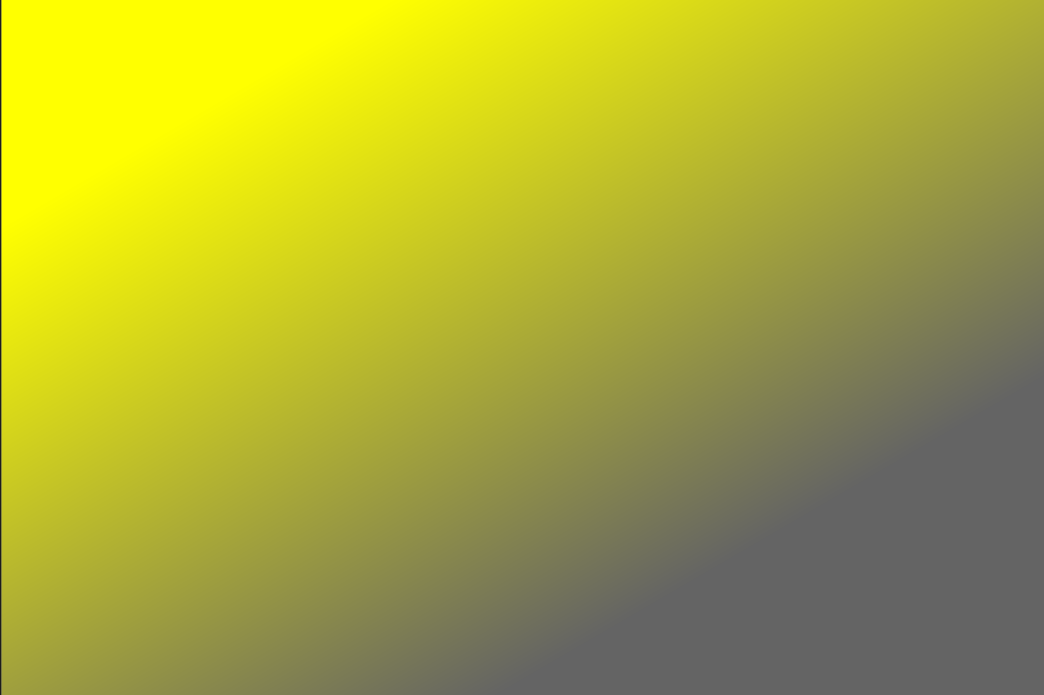
Les opérateurs ensemblistes sont utilisés pour définir la manière dont les formes groupées sont combinées. Dans les exemples suivants, (à l’exception de Somme) nous utiliserons un masque qui combine un dégradé suivi d’un chemin, pour démontrer l’effet de chaque opérateur lorsqu’il est appliqué à la forme chemin :

Par convention, dans les explications suivantes nous disons qu’un pixel est sélectionné dans un masque ou une forme s’il a une opacité strictement supérieure à zéro.
- Somme (par défaut pour les formes de brosse)
- La forme s’ajoute au masque existant en augmentant son opacité de l’opacité de la forme dessinée. Cela permet de superposer plusieurs formes (par exemple, des coups de pinceau) de faible opacité afin d’augmenter la force du masque global (par exemple, pour les opérations Dodge and Burn (éclaircir et assombrir). L’opacité d’un pixel donné est la somme des opacités des formes individuelles qui croisent ce pixel, jusqu’à un maximum de 100 %.
- Union (par défaut pour les formes qui ne sont pas des brosses)
- La forme s’ajoute au masque existant afin que le masque résultant contienne les pixels qui sont soit sélectionnés dans le masque existant, soit dans la forme ajoutée. Dans les zones de chevauchement, la valeur maximale est prise en compte :
-
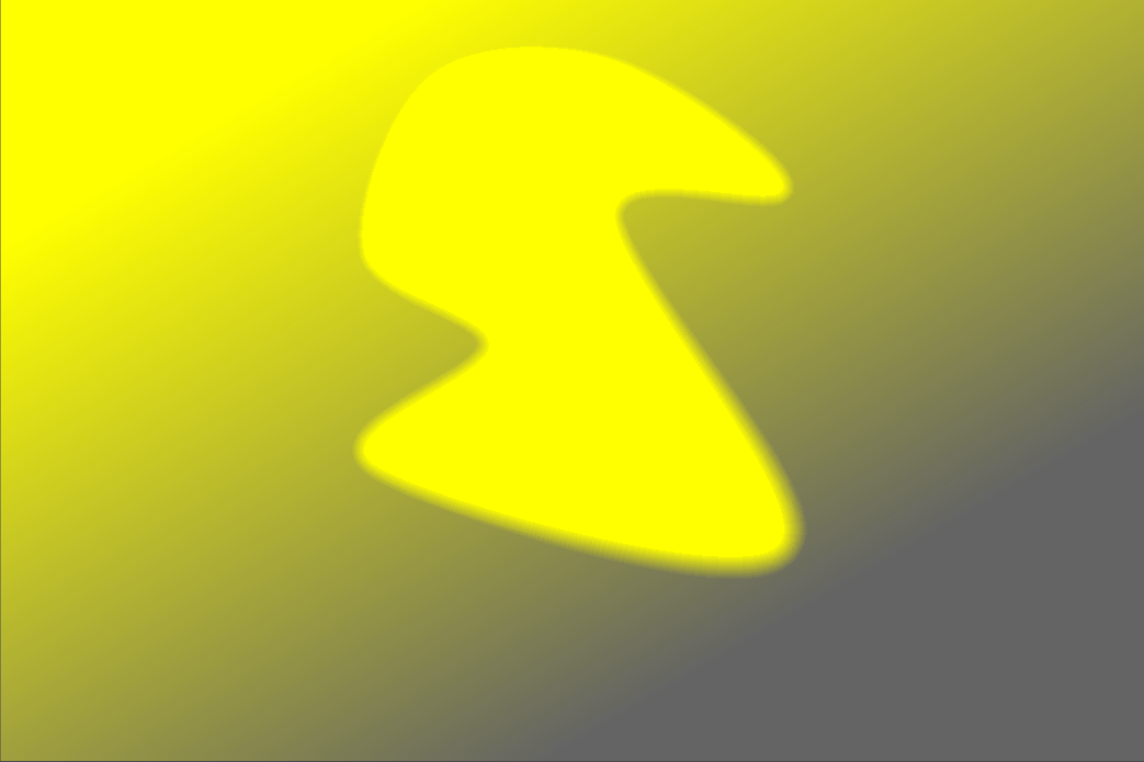
- Intersection
- La forme s’ajoute au masque existant afin que le masque résultant ne contienne que les pixels sélectionnés à la fois dans le masque existant et dans la forme ajoutée. Dans les zones de chevauchement, la valeur minimale est utilisée. Dans l’exemple ci-dessous, nous utilisons cet opérateur pour imprimer le chemin avec un dégradé :
-
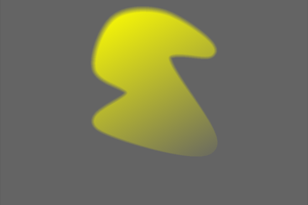
- Différence
- Dans la zone de non-recouvrement, le masque existant est inchangé. Dans le masque résultant, les pixels ne sont sélectionnés que s’ils sont sélectionnés dans le masque existant mais pas dans la forme ajoutée. Cet opérateur peut être choisi si vous souhaitez découper une région à l’intérieur d’une sélection existante :
-
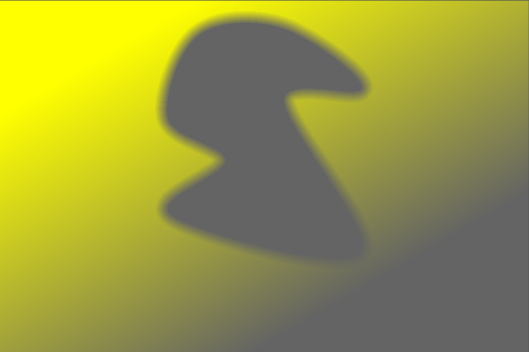
- Exclusion
- Le masque résultant sélectionne tous les pixels qui sont sélectionnés dans le masque existant et non dans la forme ajoutée, ou sélectionne ceux qui sont sélectionnés dans la forme ajoutée et non dans le masque existant. Ce qui est un ou exclusif :
-