parametric elements
Table of Contents
Parametric elements offer fine-grained selective control over how individual pixels are masked, based on their values rather than on their location. Each parametric element selects a range of values of one data channel (e.g. lightness, hue or the red channel) and assigns each pixel an opacity between 0 and 1 (100%) depending on its value in that channel.
A single element works on a single channel. To select pixels by several criteria, add several elements and combine them in a group: with an intersection operator (minimum or product), only pixels that match all elements are selected; with a union operator (maximum or screen), pixels that match any element are selected. The same channel can be used by several elements, for example to select two separate ranges of hue.
If the mask has a value of 0 for a given pixel, the input of the module is left unchanged. If the mask has a value of 1 (100%) for a pixel, the module has its full effect.
#adding parametric elements
Click one of the channel buttons in the toolbar of the mask panel to add an element for that channel. Like any new element, it is added to the selected group (or to the group of the selected element, or to the whole mask if nothing is selected). Its controls are shown in the controls section of the panel.
Rest the pointer on a channel button to preview that channel on the image before adding the element (this can be disabled in the mask options). Shift+click a button to keep the preview on while you work, and Shift+click it again to remove it. The channel is displayed either in gray-scale values or in false colors, depending on the setting in preferences > darkroom > display of individual color channels.
In the mask layout, a parametric element is shown with the code of its channel instead of an icon, and with a strip showing the range of values it selects behind its name.
#channels
The available channels depend on the module’s blend colorspace (see blending options).
Modules blending in (display-referred) Lab color space have channels for L (lightness), a (green/red), b (blue/yellow), C (chroma, or saturation, of LCh) and h (hue of LCh).
Modules blending in display-referred RGB color space have channels for g (gray), R, G, B, H (hue of HSL), S (saturation of HSL), and L (luminance of HSL).
Modules blending in scene-referred RGB color space have channels for g (gray), R, G, B, Jz (luminance component of JzCzhz), Cz (chroma, or saturation, of JzCzhz), and hz (hue of JzCzhz). The g (gray) value is calculated as a weighted average of the R, G & B channels, the exact weightings depending on the working color space being used. The JzCzhz color space is a polar representation of the Jzazbz color space, in the same way that LCh is a polar representation of the Lab space. Like the L in Lab color space, the Jz is a representation of the luminosity of a pixel that aligns with how we perceive brightness. However, the Jzazbz color space is much better for high dynamic range images and is less susceptible to hue shifts than Lab space.
See Wikipedia for more details about these color spaces.
Parametric elements are tied to the blend colorspace. If you change the blend colorspace of a module, its parametric elements are removed (darktable asks for confirmation first).
#element controls
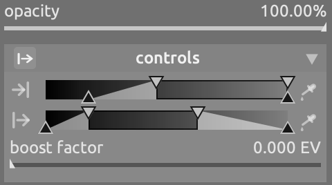
The image shows the controls with the output slider shown: the input slider is the upper one and the output slider the lower one, each with its own color picker at the right. The toggle at the left of the controls header is on.
- opacity
- How strongly the element counts in its group.
- input slider
- Select a range of values in the input data that the module receives. See range sliders below.
- output slider
- Select a range of values in the output data that the module produces, before blending. Hidden by default: click the toggle at the left of the controls section header to show it. Both sliders are applied: the element only selects pixels that match both ranges. Hiding the output slider does not switch it off – an output range that you have set keeps refining the element. Whether the output slider is shown is remembered for each element, and a second strip is shown in the element’s row while it is visible.
- boost factor
- Extend the range of values targeted by the sliders, in EV. It may be used in scene-referred editing, where luminance values may extend beyond 100%, to target highlights. This slider is only available for channels where it is meaningful.
#inspecting data channels & masks
Press the letter M while hovering over a slider to see the resulting mask for that slider overlaid on the image. When the mouse pointer leaves the slider the image returns to normal after a short delay.
To see the data of a channel itself, rest the pointer on its button in the toolbar, or Shift+click it (see above).
#linear / log mode
Press the letter A while hovering over a slider to change its display to ’log’ mode. This provides more fine control in the shadows. Press A again to toggle back to ’linear’ mode. This is not available for the hue channels.
#range sliders
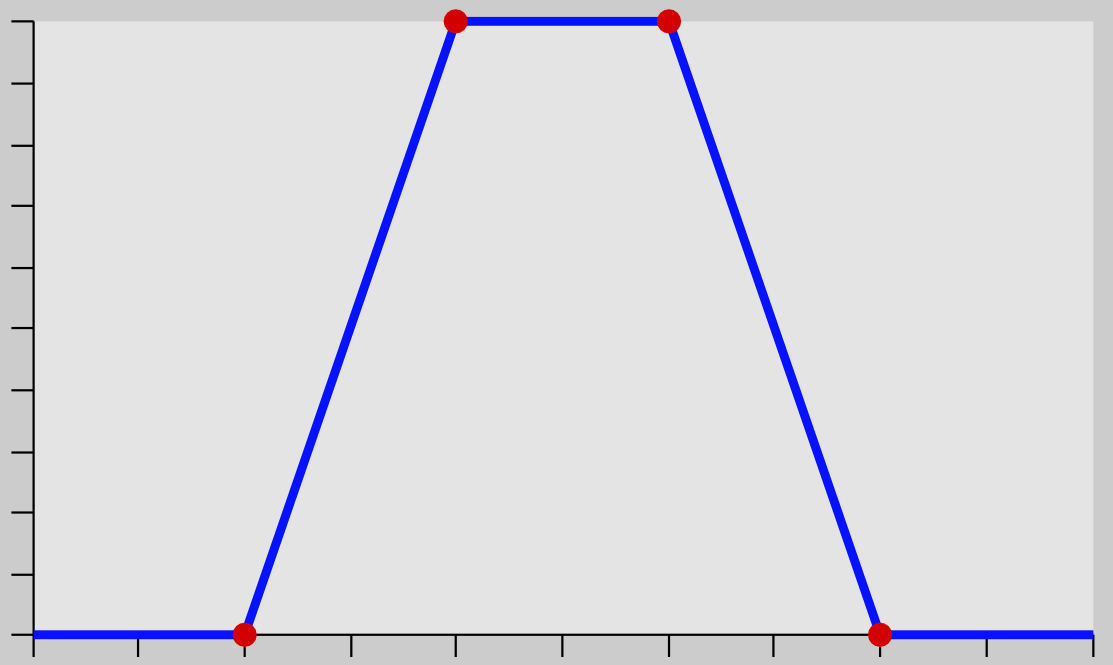
With each slider you can construct a trapezoidal opacity function. For this purpose there are four markers per slider. Two filled triangles above the slider mark the range of values where opacity is 1. Two open triangles below the slider mark the range of values where opacity is 0. Intermediate points between full and zero are given a proportional opacity.
The filled triangles, or inside markers, indicate the closed (mostly narrower) edge of the trapezoidal function. The open triangles, or outside markers, indicate the open (mostly wider) edge of the trapezoidal function. The sequence of the markers always remains unchanged: they can touch one another but they cannot switch position.
Drag a marker to move it. Right-click a marker to type a precise value. Double-click the slider to reset it.
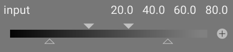
In their default state all markers are at their extreme positions, and the element selects the whole range of values (giving an “all at 100%” mask). Move the markers inwards to gradually exclude more and more parts of the image except for the remaining range. While the range still covers the whole span of its channel, the element does not restrict anything, and a warning sign next to its name says so.
#inverting an element
Click the
 invert button on the element’s row to invert it: the element then deselects the chosen range of values instead of selecting it. The markers of the sliders swap to show this, as in the following images.
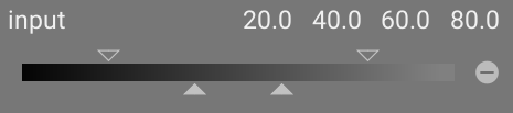
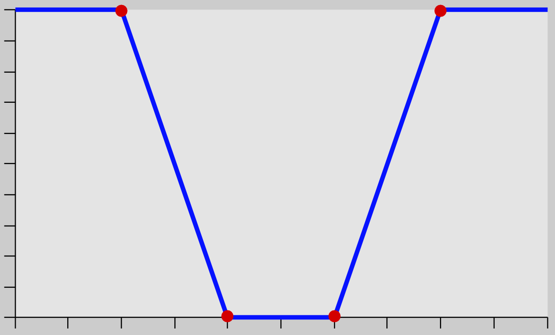
To invert all parametric elements of a group at once, Shift+click the invert button of the group. To invert the combined result of a group instead, click the group’s invert button.
#pickers
Each slider has its own picker at its right.
- Click the picker, then drag a rectangle on the image, to set the slider’s range automatically from the values in that area.
- Ctrl+click to pick a color (point) from the image and display its value on the sliders, without changing them; Ctrl+Shift+click to do the same for an area.
When reuse the last picked area is enabled in the mask options, clicking the picker of another element sets its range at once from the area last picked in the same module: pick an area for one channel, then simply click the picker of the next one.
#reusing parametric elements
Use copy parametric channel in the import menu to copy a parametric element from another module. Only modules that use the same blend colorspace are offered; elements set up in another blend colorspace are listed but cannot be picked.
Note: A parametric element evaluates the input of the module it belongs to. Using the same parametric element in modules at different stages of the pixelpipe can therefore give different results, because the image they see is different.